MapTools Large Classroom Training Aids
I have spent a lot of years teaching land navigation in both classroom and field situations. One of the things I found useful was to have large versions of some of the small tools that the students use. I could hold them up and demo what I wanted the students to be doing with their tools. I was able to buy a “big demo compass” from Brunton many years back and I made larger versions of a few MapTools products to use.
Brunton doesn’t sell their “big compass” any more and gluing bits of printed overhead transparency material to plexiglass sheets was too tedious do make more than the few tools I needed. At one point I had some GTA and SuperGTA tools made in a large format at a local screen printing shop. I was cutting them out using a ShopBot CNC machine at a local maker space. They were not big sellers and eventually the maker space closed, ending my ability to make them.
So now in 2022, MapTools has the equipment to print on clear plastic stock one sheet at a time, and to laser cut the printed results as well. So now I can once again offer our large classroom training aid products.
Links to the current products…
- UTM Grid Style Classroom Training Aid
- UTM Slot Style Classroom Training Aid
- Corner Ruler Style Classroom Training Aid
- Mini Corner Style Classroom Training Aid
- Map Ruler Style Classroom Training Aid
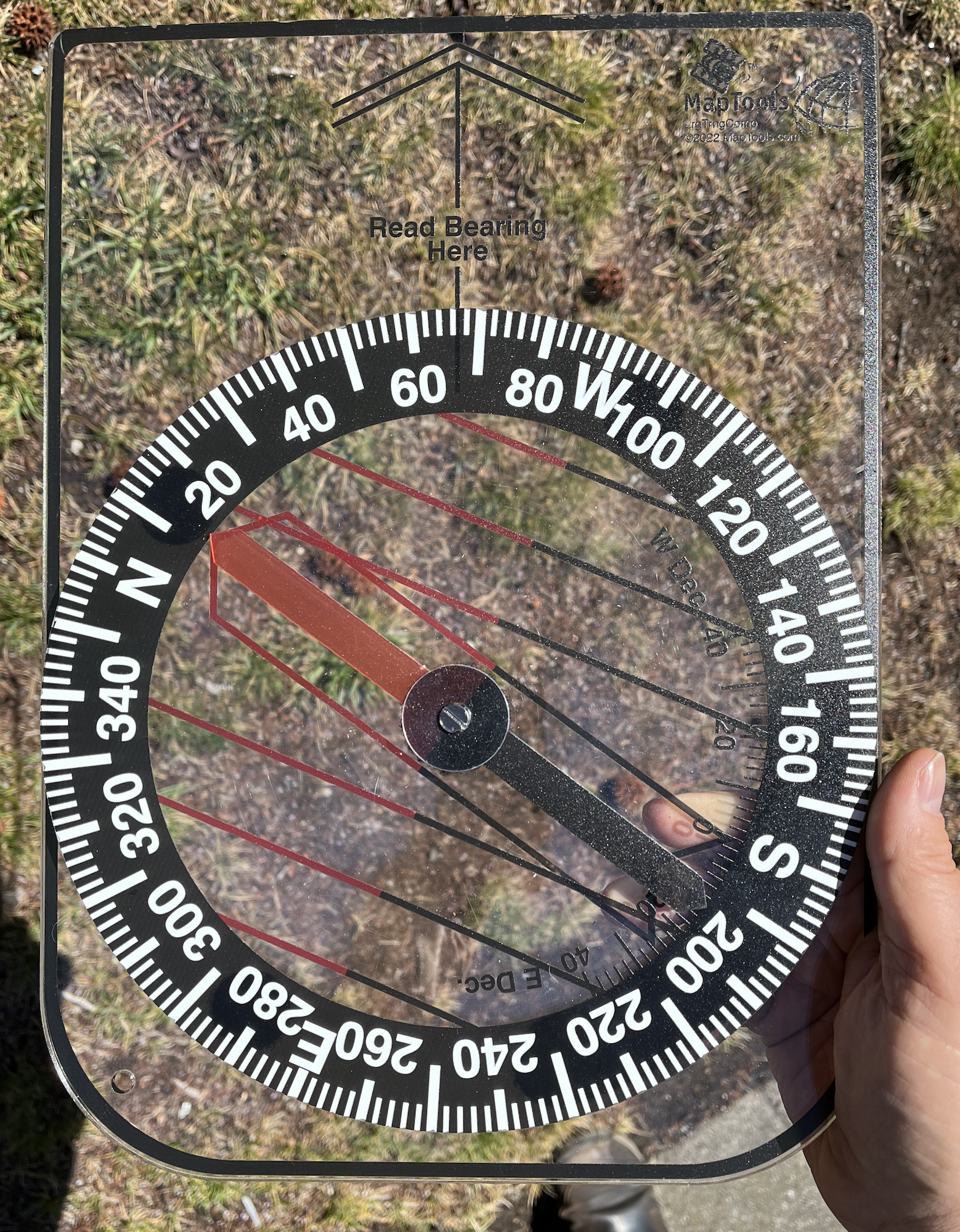
- Compass Classroom Training Aid
In the planning and design stage are:
- GTA and SuperGTA military protractors
Here are some photos and explanation of the tools as they would be used for training.
Making a “map” to use with the UTMGrid and UTMSlot tools:
Both of these tools have small holes at the corners of the 1 kilometer grid.
-
Step 1 - Mark the corners of the first grid.
If the classroom has a white board, I’ll likely be doing this on the whiteboard with a whiteboard marker. Otherwise I’ll be using a big sheet of white paper. I usually tear off a piece that’s about 3 ft. by 4 ft. in size.

-
Step 2 - Move the tool over 1km and mark the corners of the next grid.
Repeat this until you have a map the size you want to use.

-
Step 3 - Draw in the grid lines, and add the UTM coordinate labels.


-
Step 4 - Add a few features, and the map is ready

The UTMGrid and UTMSlot training aids are both the same scale. The plan is to make the UTM Mini Corner, the UTM Corner Ruler, and the kilometer edge of the Lat Lon ruler all the same scale. That way you can demonstrate how the different tools work, using the same practice map. The tools have a scale of 1:6,369.
The GTA and SuperGTA tools are both larger tools. Since our print size is limited to a width of 12 inches, I’ll have to make them a different scale.
If you want something more "map like" than a white background with some grid lines and labels, you can make a topo map at 1:6,369. Here is a link to a training map I made using CalTopo.com You can get it printed on you own, or you can have us get it printed and laminated for you. I use PosterBrain.com Their current pricing (April 2022) is $54 for printing, $12 for lamination, $8 for Priority Mail shipping. We charge more than they do, but then we are doing the work. It's easy and you should really do it yourself.
Some tips for making your own CalTopo Training map
- - You’ll need a paid subscription to generate large PDFs
- - I created a 36" x 48" map.
- - Use a 1:6,369 scale. (Chose Custom Scale and enter 6369.)
- - Use 1km UTM Grid lines
- - If you are using a USGS scanned base map with printed UTM Grid lines, you’ll likely want to use the NAD27 datum or you will have 2 sets of grid lines, which makes for a confusing demo.
- - The coordinate labels will be in a tiny type size. Plan to add them by hand if you want the class to be able to see them.
- - PosterBrain has a max file size of 100 MB. I exported the pdf file as a 150 dpi TIFF file to get it under 100 MB.
Laminate the map, so you can reuse it.
Measuring coordinates of points on the map.
Grid tool

Use the SW corner of the grid to determine the coordinates of the grid square. The green triangle is in the 1km grid square at 246,000km E and 4,279,000m N. Place the tool in the grid square and use it to measure within the grid, we see that the green triangle is in the 100m square that is 200m further east and 500m further north. So the resulting UTM coordinate of the green triangle is 246,200m E 4,279,500m N.
If we were demonstrating MGRS or USNG coordinates, we would take the first two digits of the easting an northing using the large type digits at the SW corner of the grid square. (or the 10,000 and 1,000 meter digits, if you do not have the large type hints.) So the grid square is 46 79. We would get the third digit (the 100m value) using the tool. The green triangle is at 462 795 in 100m abreivated MGRS or USNG coordinates.
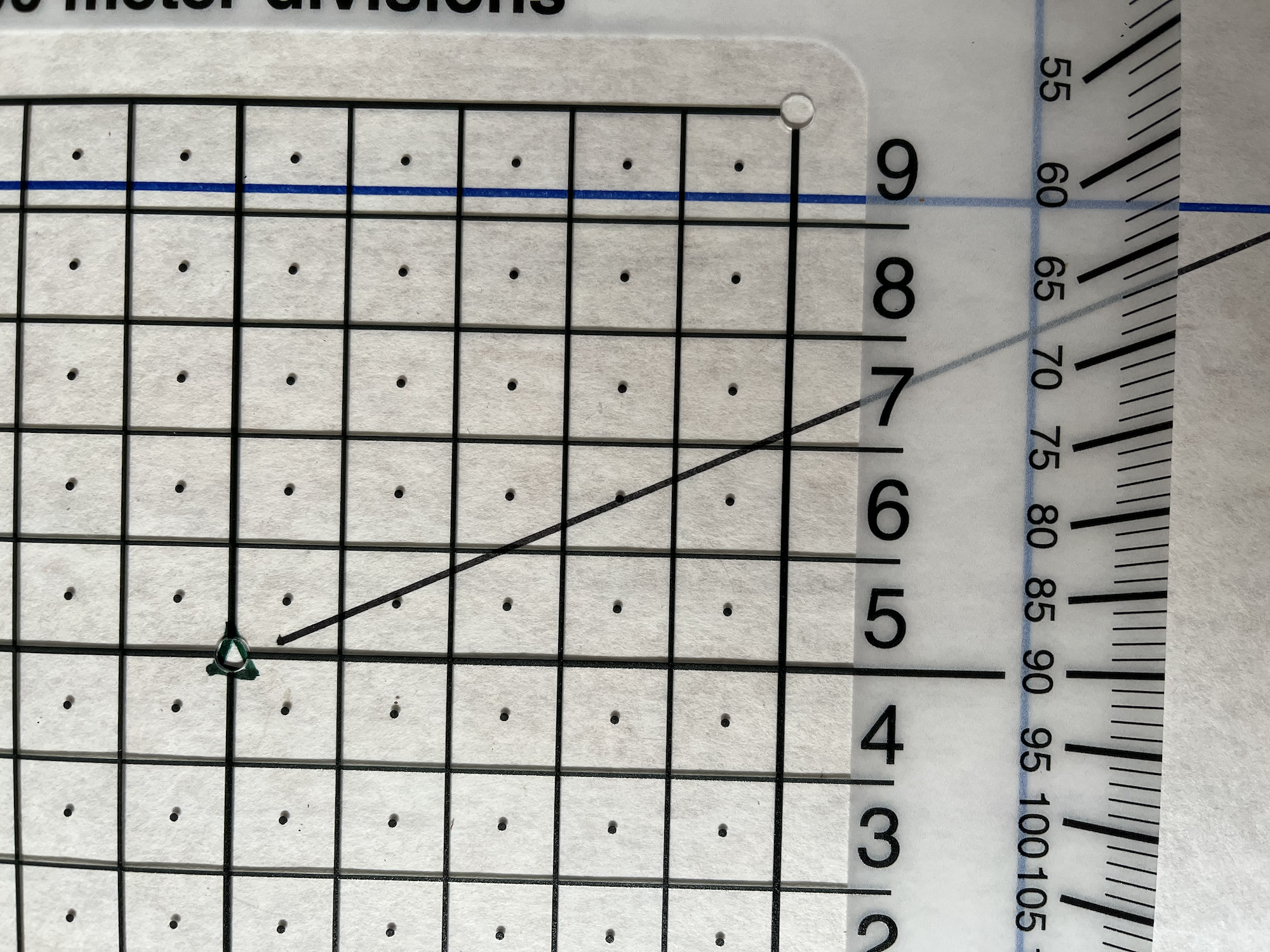
The red X is at 248,600m E 4,280,600m N UTM or 486 806 MGRS or USNG 100m. The red X is right on the line between the 500m N and 600m N squares on the tool. You have to choose, I went with the larger northing.
Slot Tool
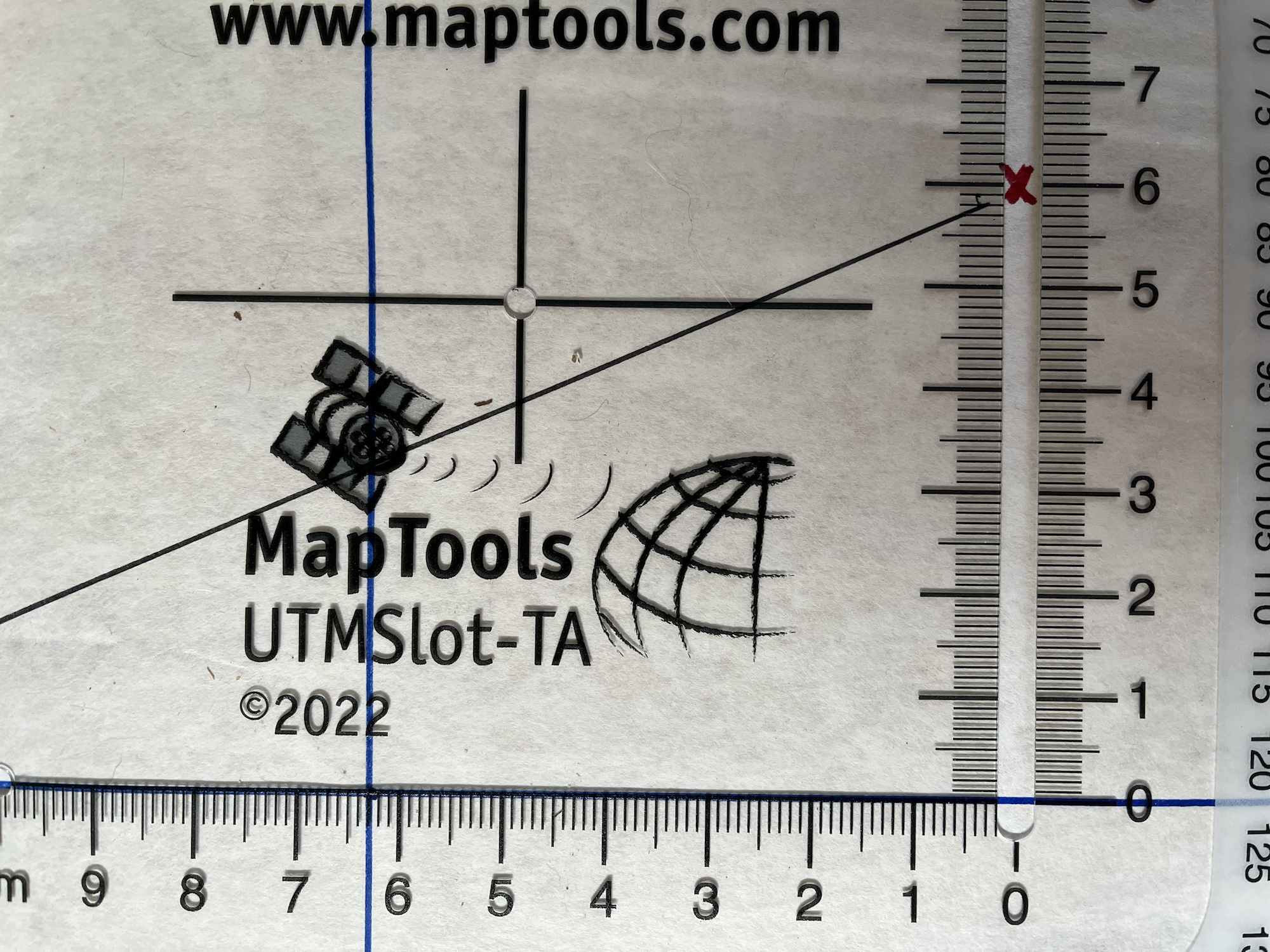
Using a slot style tool, we can measure the coordinates of the red X with a 10 meter precision. Again get the grid coordiantes using the SW corner of the grid. The 1km grid can be described with the coordinates 248,000m E 4,280,000m N UTM or 48 80 MGRS or USNG 1000m
Place the bottom scale of the slot tool on the southern edge of the grid square. Check that the top of the 1km scale of the tool is on the northern grid line. (if it's not, your toom doesn't match you map scale.) Slide the tool east or west until the red X in centered in the slot. Measure the easting distance within the grid where the western grid line cross the scale on the bottom of the tool. In this case three tics past the 6, or 630m further east. Measure the northing distance within the grid at the red X. In this example, right at the 6, or 600m further north.
The red X is at 248,630m E 4,280,600m N UTM or 4863 8060 MGRS or USNG 10m.
Partial Grids
Plotting a coordinate onto the map
Grid Tool
Slot Tool
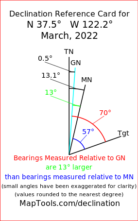
Using the protractor to measure a bearing between two points

Using the protractor to plot a bearing from a know point
Plotting the back bearing
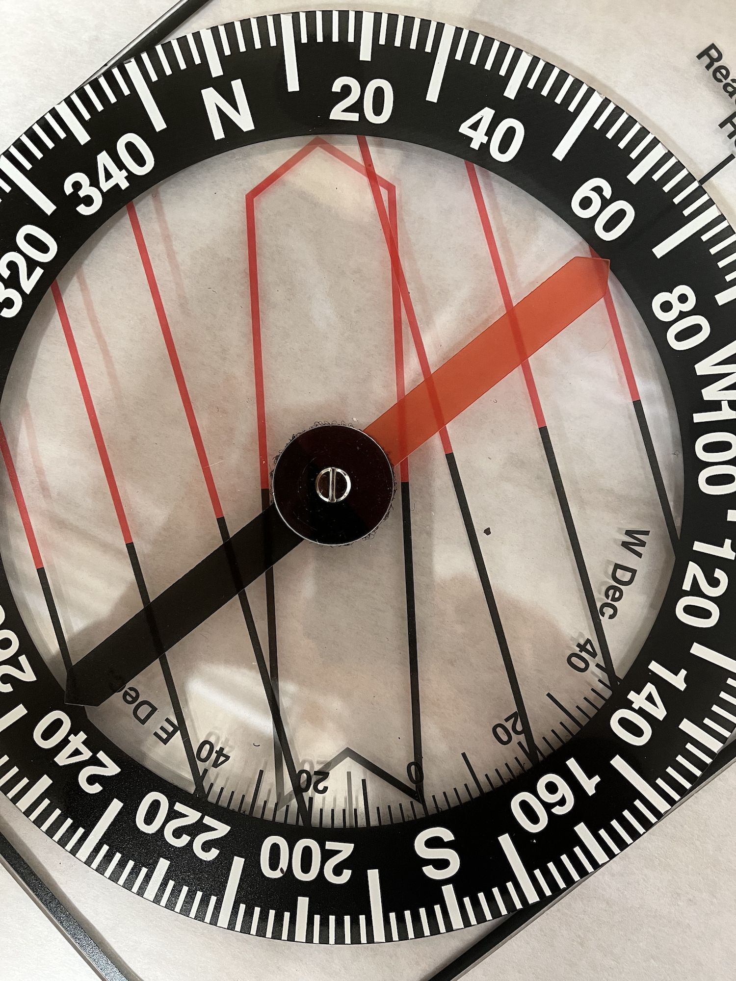
Using a compass to measure a bearing
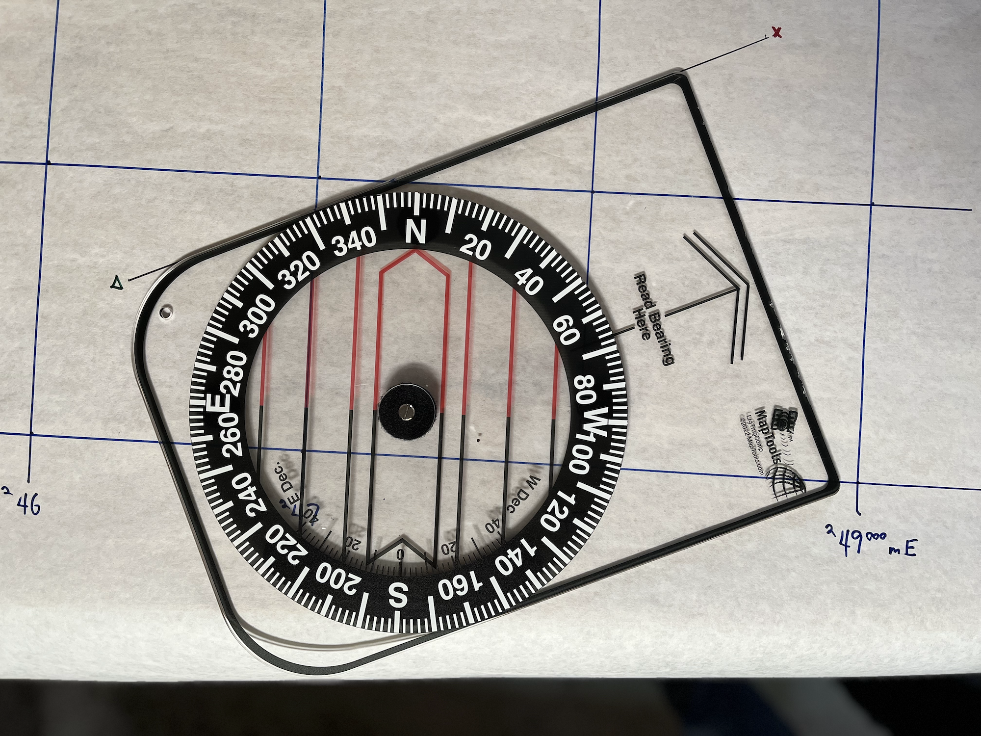
Using a compass to plot a bearing
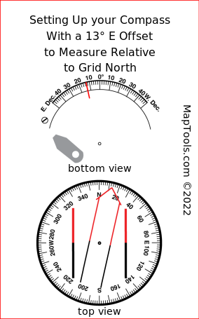
The compass set up for grid north readings ready to follow a bearing